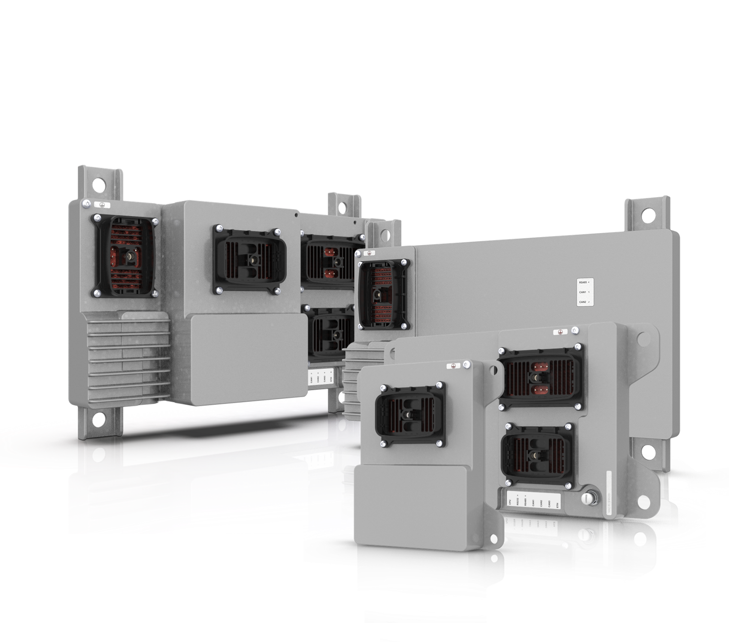
Woodward E6 - replacement for EGS-01, EGS-02 and E3.
EGS-01 obsolute
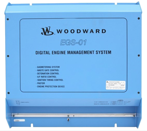
EGS-01 is an electronic control system for a more accurate and flexible metering system for gas engine to keep the right emmissions and preformance.
The EGS 01 is a state-of-the-art control module for stationary gas engines. It can be used to control the gas flow in relation to the air flow of an engine, at any load and speed condition. The EGS 01 control is capable of keeping gas engine emissions constant over a longer period of time. And the EGS control is not sensitive to the quality of the gas or the gas pressure and temperature. This is accomplished by the patented gas quality closed loop (lean burn) algorithm or lambda sensor.
The EGS 01 control can be applied on in-line and V-type engines of any power output, naturally aspirated or turbocharged. The control can be easily programmed with the EGS monitoring program, and it covers the wide range of gas qualities, from landfill gas to propane. Even a significant change in gas quality during normal operation of the engine will be compensated for by the control.
The E6 main replace the EGS-01 with all his functionallaty. It can be exteneted now with ignition, knock, thermocouples and extra I/O.
E3-FA, E3-Rich and E3-TRIM obsolute
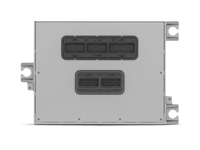
E3 Full Authority (PCM128HD) replaced the EGS-01 with all his functionallaty. The E3 is now obsolute and replaced by the E6. It can be exteneted now with ignition, knock, thermocouples and extra I/O.
The E3 TRIM is replaced by the same E6-main and has the same software as the Full Autority. Only configuration is different.
The E3 RICH is replaced by the same E6-main, but has different software.
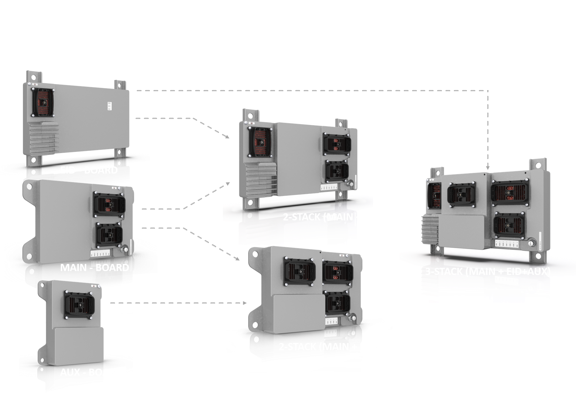
The E3-TRIM and E3-Rich had ignition with Smart Coils option, those will be replaced by the E6 2-stack, MAIN +EID.
EGS-02 (733) EGS-CAT or EGS-MHI
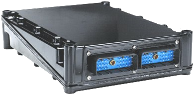
EGS-02 Full Authority (733) replace the EGS-01 with all his functionallaty and has special functions for the Caterpillar and MHI engines. (NOx sensor, pre-chamber control).
The EGS-02(733) will be replaced by the E6. It can be exteneted now with ignition, knock, thermocouples and extra I/O.
Replacing the EGS01/02 Gas Engine Control with E6 Lean Control System
Woodward’s EGS-01 and EGS-02 controls are no longer in production, and have been replaced by the E6 Lean application. The EGS Conversion application replaces EGS-01/02 in Full-authority, Lambda >1, Mono-control systems.
The purpose of this application note is to provide guidance on retrofitting an EGS-01/02 installation or design with the E6 Lean. It is intended to supplement the EGS Control System Application Manual 26321 and the E3 Full Authority System manual 26538, which details control installation, operation, calibration, and troubleshooting of the (EGS-O2=E3).
Assumptions
Introduction
Woodward’s E6 Lean can be used as a functional replacement for the EGS-01/02/E3 FA FB control. The E6 Lean was designed to replace an EGS-01 or EGSO2 system with minimally changes to the existing wiring.
Differences Summary
Due to internal control design differences, the customer wiring to the control terminals is different. This application note illustrates the differences in wiring, sensors, communication interfaces, and Service Tool.
Inputs Differences
| Inputs | EGS-01 | EGS-02 | E3 | E6 Lean | E6 Options |
|---|---|---|---|---|---|
| Power supply | Nominal: 10–32 Vdc, minimum 7 Vdc | Nominal: 8–32 Vdc, minimum 6 Vdc; 15 W nominal (not including driven loads) | Nominal: 18–32 Vdc, minimum 12 Vdc for 30 seconds, 9 Vdc for 100ms | ||
| Speed Sensor | VR or Active Sensor | VR or Active Sensor | VR or Active Sensor | VR or Active Sensor | |
| ALL ANALOG INPUTS | Two-wire grounded or ungrounded | One wire common return | Some Analog Inputs may be used with a two-wire ungrounded (loop powered) transducer or an isolated (self-powered) transducer. Some One wire common return. | AUX: 0-25 mA and/or 0-5 VDC | |
| MAT | PT-100 | PWM or 4-20 mA | Thermistor NTC | Thermistor NTC | AUX: Thermocouples and RTD |
| MAP | 0–20 mA, 0–10 V or 0–5 V | PWM or 0-20 mA | 0–5 Vdc | 0–5 Vdc | |
| KW | 0–20 mA, 0–10 V or 0–5 V | 0–20 mA, J1939 with Easygen | 0–5 Vdc, J1939 with Easygen | 0–5 Vdc or 4-20 mA, J1939 (with Easygen) | |
| CH4% | 0–20 mA, 0–10 V or 0–5 V | 0–20 mA | 0–5 Vdc | 0–5 Vdc or 4-20 mA, Modbus | |
| Load Reference | 0–20 mA, 0–10 V or 0–5 V | 0–20 mA, J1939 with easYgen | 0–5 Vdc, J1939 with easYgen | 0–5 Vdc or 4-20 mA, J1939 (with easYgen) | |
| Speed Bias | 0–20 mA, 0–10 V or 0–5 V | 0–20 mA, J1939 with easYgen | 0–5 Vdc, J1939 with easYgen | +/-2.5Vdc , 0–5 Vdc, 4-20 mA, PWM, J1939 (with easYgen) | |
| Throttle Position Sensor | 0–20 mA, 0–10 V or 0–5 V | 0–5 Vdc | 0–5 Vdc, J1939 | ||
| Ignition Timing Input | CAN/IC-92X only | CAN/IC-92X only | CAN/IC-92X only | Internal to EID Ignition Only | J1939 |
| Detonation Protection | CAN/FireFly™ only | Internal to AUX Knock Only | J1939 | ||
| UEGO | 0–2.5 V, 0–5 V | Needs Converter box for 0–5 Vdc signal input (NGK UEGO) | Bosch LSU 4.2 sensor directly or needs Converter box for 0–5 Vdc signal input (NGK UEGO) | Bosch LSU 4.9 sensor directly or needs Converter box for 0–5 Vdc signal input (NGK UEGO) | |
| Potentiometer | Integrated into the control | External 1 kΩ to 10 kΩ 3-wire pot | External 1 kΩ to 10 kΩ 3-wire pot | ||
| Thermocouple | Two (2) J or K type | Cannot use thermocouple | Cannot use thermocouple | Eight (8) J or K type | |
| ALL DISCRETE INPUTS | 0–6 V = FALSE 4-32 V = TRUE |
Sinking Close to J1-A24 to activate | Based on Hardware Jumpers Sinking (E3) > 9 Vdc = “OFF” < 2 Vdc = “ON” or Sourcing (EGSO1) >9 Vdc=TRUE, <2 VDC=FALSE |
||
| Circuit Breaker Aux | Not available | Connect to Gen circuit breaker aux, used for multiple dynamics | Connect to Gen circuit breaker aux, used for multiple dynamics | Connect to Gen circuit breaker aux, used for multiple dynamics | |
| Mains Circuit Breaker Aux | Close only when Gen & Mains is closed, used for activation of kW load control | Connect to mains circuit breaker aux, used for multiple dynamics and activation of kW load control | Connect to mains circuit breaker aux, used for multiple dynamics and activation of kW load control | Connect to mains circuit breaker aux, used for multiple dynamics and activation of kW load control | |
| Fuel On | Activates control by opening throttle and TecJet™ | Activates control by opening throttle and TecJet™ | Activates control by opening throttle and TecJet™ | Activates control by opening throttle and TecJet™ | |
| Raise/Lower | Changes internal reference | Changes internal reference | Changes internal reference | Changes internal reference | |
| Rated/Idle | Changes internal reference | Changes internal reference | Changes internal reference | Changes internal reference | |
| Fault Reset | >10mA resets faults | Sinking Close to J1-A24 to activate resets faults | Standard DI resets faults Sinking > 9 Vdc = “No Reset” < 2 Vdc = “RESET” |
||
Outputs Differences
| Outputs | EGS-01 | EGS-02 | E3 | E6 Lean | E6 Options |
|---|---|---|---|---|---|
| Throttle Command | PWM - Push-Pull, 0–24 Vdc, 1000 Hz | PWM - Push-Pull, 0–5 Vdc, Frequency variable | PWM - Push-Pull, 0–20 Vdc, 30–3000 Hz | ||
| Wastegate Output | PWM - Push-Pull, 0–24 Vdc, 1000 Hz | PWM - Push-Pull, 0–5 Vdc, Frequency variable | PWM - Push-Pull, 0–20 Vdc, 30–3000 Hz | ||
| TecJet Power | 6 A steady state, 10 A peak for 1 sec | None | None | None | |
| TecJet Keyswitch | 10 mA max, activates the TecJet when the engine is rolling | Use one of the speed switch outputs and an interposing relay | Use one of the speed switch outputs and an interposing relay | Use Master Power Relay Driver +20Vdc when active | |
| Fault Outputs | Form C, dry contacts | Low side relay drivers | Low side relay drivers | ||
| Major Alarm | 15 Open from 14 when Engine Shutdown Condition is True 16 Close to 14 when Engine Shutdown Condition is True |
Closes to Ground on Engine Shutdown Condition | J1-006 De-energizes on Engine Shutdown Condition | ||
| Minor Alarm | 52 Open from 51 when Engine Alarm Condition is True 53 Close to 51 when Engine Alarm Condition is True |
De-energizes on Control Warning Condition | J1-005 De-energizes on Control Warning Condition | ||
| CPU OK | 55 Open from 54 when System Ready Condition is True 56 Close to 54 when System Ready Condition is True |
De-energizes on Control Watchdog Condition | J1-102 Energizes on Control when power supply input is in Range | ||
| Speed Switches | None | Individually configurable for speed limit activation | Individually configurable for speed limit activation | Individually configurable for speed limit activation | |
| AUX Power | 5 Vdc, 70 mA for sensor power | 5 Vdc, 300 mA for sensor power | 5 Vdc, 300 mA for sensor power | ||
| LED Indications | Power, Fuel On, Alarm, Shutdown | None | None | CPU, RS232, RS485, CAN1, CAN2, CAN3, Ethernet | |
Woodward gas engine control specialist ![]()